Showing posts with label Electricals. Show all posts

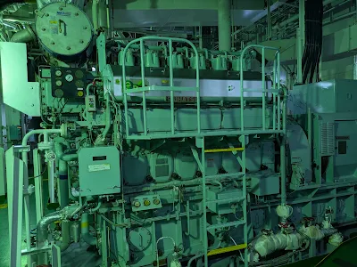
Axial play in Diesel Engine

Axial play in a big end bearing refers to the amount of movement of the connecting rod along the crankshaft axis. It's also known as end play or axial clearance. 
Excessive axial play can cause vibrations, misalignment, and potential failure, while insufficient play can lead to binding and premature wear.

What is Axial Play?

In bearings, axial play is the movement of the inner ring relative to the outer ring along the bearing axis. In the context of a big-end bearing, it's the movement of the connecting rod cap along the crankshaft axis.

Why is it important?

Axial play is a crucial factor in the performance and longevity of bearings.

Consequences of excessive play:
Vibration and Noise: Excessive axial play can cause vibrations and noise due to the connecting rod moving excessively within the big end bearing.

Misalignment: The connecting rod may not be properly aligned with the crankshaft, leading to increased stress and wear.

Potential Failure: In severe cases, excessive axial play can lead to bearing or connecting rod failure.

Consequences of insufficient play:

Binding and Friction: If there's not enough axial play, the connecting rod can bind with the crankshaft, causing excessive friction and heat.

Premature Wear: Insufficient play can lead to premature wear of both the big end bearing and the crankshaft.

Measuring Axial Play:
The axial play in a big end bearing can be measured using a dial indicator.

Proper Installation: Ensure the big end bearing is correctly installed and torqued to the manufacturer specifications.

Normal Range:
The acceptable range of axial play for big-end bearings varies depending on the engine and application.


Electrical checks on a Electric Motor

Here are some basic checks that can be done on a running motor when you take your rounds

1) Pressure Gauge
  • Monitor suction and discharge pressure.
2) Ammeter Reading
  • Check the current drawn while running.
  • Pay special attention to the current during motor start-up.
3) Temperature and Vibration
  • Touch and feel to check for abnormal heat or vibration levels.
4) Noise: Listen for abnormal sounds such as:
  • Grinding
  • Scraping
  • Humming
5) Physical Condition
  • Inspect for visible damage, corrosion, or water ingress.

Two important electrical tests that can be done on a Motor/equipment when the power is isolated or when overhauling the  motor are

  1. Continuity test 
  2. Insulation Resistance Test

Continuity Test

  • Purpose: This test ensures that there is a complete and unbroken path for electrical current to flow through a circuit.It means there is a low resistance value between the points being tested, indicating a closed circuit
  • Tools:  A continuity test can be performed with a multimeter
  • Show a low resistance reading if the circuit is complete.
  • Why is the Continuity test important?

  • They help pinpoint the source of faults in circuits, allowing for faster and more accurate repairs.
  • By detecting potential problems early, they help prevent larger issues and reduce downtime.
  • They can test simple components like switches, fuses, and wires to ensure they are functioning correctly.

Insulation Test

  • Purpose: This test measures the resistance of the insulating material around electrical conductors, like cables. It determines how well the insulation prevents current from leaking or flowing through the insulating material.
  • Tools: An insulation test is carried out using a megger
  • Usually done with a megger test with a test voltage of 500V DC for a 440V AC motor.

  • Why is the Insulation test important?

  • Crucial for ensuring the safety and reliability of electrical systems by verifying the integrity of insulation materials.
  •  They help prevent electrical hazards like shocks, short circuits, and fires, as well as equipment downtime. 
  • Regular insulation testing can also identify potential problems before they become major failures, allowing for timely maintenance and repairs.

Continuity test on a motor

Prove the equipment/motor is dead
  • Set the Multimeter to Voltage Mode. Turn the dial to AC Voltage (V~ ~). Make sure it's set to a range higher than the system voltage (e.g., 600V range for a 440V system).
  • To verify the Multimeter Works, test it on a known live circuit to make sure it reads voltage correctly.
  • Open the motor terminal box.Using the multimeter probes, test:Phase-to-phase: (e.g., L1–L2, L2–L3, L1–L3)Phase-to-earth/ground: (e.g., L1–E, L2–E, L3–E)
  • Expected result: 0 volts on all tests.
After proving the equipment/motor is dead using a multimeter
  •  Turn the dial to the continuity setting
  • If using a digital meter, you may hear a beep when continuity is detected.
  • Test the Multimeter: Touch the two multimeter probes together.You should hear a beep or see 0 ohms (or very low resistance), indicating the meter is working.
  • Access Motor Terminals,open the terminal box of the motor.Identify the motor winding terminals (typically marked U, V, W or T1, T2, T3).
  • Test Winding Continuity touch the probe you want to test for continuity.
  • You should get a low resistance reading (a few ohms), indicating good continuity

Insulation test- Using megger-tester

Usually done with a megger test with a test voltage of 500V DC for a 440V AC motor.

The test is performed by applying a current-limited DC test voltage between the conductors (e.g., Windings) and the Ground. Any current leakage is to be measured across the insulation’s dielectric materials. The current may be measured in milliamps or microamps and then calculated into Meg-ohms of resistance. The lower the current value, the greater the insulation resistance.
  • The equipment/motor needs to be disconnected and locked out according to standard safety procedure
  • Check megger function by shorting probes—pointer should indicate 0 MΩ.
  • Prove the equipment/motor is dead using a multimeter or a megger tester. If using a megger test, connect the probes to a pair of conductors or motor terminals. If the pointer deflects, that means the circuit is live
  • After ensuring the conductors are dead, it is safe to press the button and log the phase-to-phase insulation resistance. 3 readings should be measured U-V, V-W, W-U
  • Then measure the phase to earth insulation resistance reading U-E, V-E, W-E
  • The higher the resistance, the better the insulation.
  • Results are typically in Meg-ohms (MΩ).

What does CCA and Ah in battery mean

Cold-cranking amps (CCA)

It is a battery rating system that defines the battery's ability to start an engine in cold conditions.

What does a 400 CCA battery mean?

It means a battery rated 400 cca will give 400 amps of power for 30 seconds at 0 deg cel maintaining a voltage of 1.2v per cell or 7.2v for a 12v battery

And  battery rated 200 CCA will give 200 amps of power for 30 sec at 0 deg celsius, maintaining a voltage of 1.2v per cell

How much CCA do I need?

The thumb rule is one amp per cubic inch of engine displacement.
  • “Higher CCA = Better cold starting performance.”


Why do batteries deteriorate at cold temp?

At cold temperatures, the reaction in the battery slows down impacting its ability to start the I.C. engine.
LO viscosity increase at lower temp making it harder to pump oil and start the engine. This makes a situation where your battery has to work harder to start the engine.
It is always better to have a higher CCA-rating battery for marine applications.

Ah rating?

Ah typically measures batteries' total energy-storing capacity.

A 100 Ah battery is capable to deliver10 amp for 10 hrs before the voltage drops to a standard value of 1.67 volts per cell or 10.02 volts for a 12v battery.
Similarly, 50Ah would supply 5 amps for 10 hrs

Ah = Amps x hours
Amps hour(Ah)= Current(I) x Discharge time (T)

CCA VS Ah

CCA is the ability of the battery to deliver a burst of power over a short time like a sprinter

Application- ➡Starting lifeboat engine, Emergency generator, etc.

Ah is the ability to deliver power over a length of time like a marathon runner. 

Application➡GMDSS battery, general service battery, etc (deep cycle application)

Power factor-Basics

 In AC circuits, the power factor is the ratio of the Real/true power that is used to do work and the apparent power that is supplied to the circuit.

  • The power factor can get values in the range from 0 to 1.
  • When all the power is reactive power with no real power (usually inductive load) - the power factor is 0.
  • When all the power is real power with no reactive power (resistive load) - the power factor is 1.
Power factor=True power/Apparent power
=watts/volts-amps
=KW/KVA
Real power is the actual power consumed or dissipated due to the resistance load and is 
  • Measured in Watts
  • Symbolized by the capital letter P, as always

Apparent power is a phantom power combination of reactive power and true power and it is the product of a circuit’s voltage and current, without reference to phase angle,

  • Measured in the unit of Volt-Amps (VA) 
  • Symbolized by the capital letter

Why should I improve the power factor

Improving the power factor can improve the current-carrying capacities

  • Improve voltage drop in equipment or even cancel completely the (inductive) reactive current in upstream conductors
  • Reduce power loss/heat generated
Losses in cables are proportional to the current squared. The reduction of the total current in a conductor by 10% for example, will reduce the losses by almost 20%.
  • Reduction in cable size
  • Lower electric bill and save money

Generator safety and protection

The protection device is built into the main alternator circuit breaker to safeguard both the individual alternator and distribution system


1)Overcurrent protection

The alternator has overcurrent protection but the main consideration is to maintain the supply of power for as long as possible. The breaker is designed in such a way that is trip instantaneously only in the event of high overcurrent due to a short circuit.

When an overcurrent is not so high a delay with inverse time characteristic allow an interval of time (or a time delay )before the breaker is opened during this time delay the overload may be cleared, hence allowing the supply of power for as long as possible giving rise to IDMT RELAY(inverse definite minimum time Relay)

REASONS FOR OVERLOAD


  • Due to serious fault in the switchboard causing the high current fault
  • Partial/Straight overload due to starting of big motors

2)Preferential trips

This trip is designed to disconnect non-essential load (like ventilation fan, HVAC, reefer system, etc) in the event of partial/straight overloading with the aim to prevent operation of main breaker trip an loss of total power failure.
  • Non-essential load are grouped together and disconnected at timed intervals arranged at 5,10,15 seconds
  • Operated at a relay set at about 110% of normal fault load
Das pot arrangement is an older design provided to give a time delay or time lag for the relay to operate, it consists of a piston moving in a cylinder with silicone fluid. The piston moves up or down as the silicone fluid is displaced from top to bottom through a small hole or by the way of clearance around it.time delay can be adjusted bu the size fo the hole or clearance

3)Reverse power trip

It is intended when the alternator is running in parallel operation, this trip will release the breaker and prevent the motoring of the alternator if a reversal of power occurs.
Such a device is used to prevent physical damages to the prime mover, which has shut down due to mechanical faults.

For a detailed explanation

4)Under voltage trip

  • It helps to prevent the closure of the circuit breaker by mistake when the alternator is dead.
  • This is fitted in the alternator which is arranged for parallel operations, the instantaneous operation of this trip is necessary to prevent the closure of the breaker.
  • It also gives protection against the loss of voltage while the machine is connected to the switchboard.

Electrical Shore supply

Shore supply is generally required in dry dock, to supply the vessel with power when the onboard generator and auxiliary system goes offline for maintenance. There must be a suitable connection box conveniently located at the entrance of accommodation or the emergency generator room to connect the shore supply.

The connectin box may have the following


  1. Circuit breaker or a switch and fuse to protect the cable linking the connection box
  2. Data plate depicting the ships electrical system(voltage and frequency)
  3. Voltmeter to indicate the voltage
  4. Frequency meter to indicate the frequency
  5. Phase sequence indicator usually a lamp to indicate that the shore power is available for connection to the bus bar
  6. An interlock with the MSB to ensure the breaker is not closed when the ship's generator is connected.

Problems with higher frequency and voltage

  • A higher frequency will cause the motor to run faster and overheat.]
  • A higher voltage may generally cause equipment to draw higher current and overheat and may cause a motor to accelerate more rapidly and this may over stress-driven load

If the shore supply frequency differs

If the shore supply frequency differs with the ship's normal frequency then ideally the shore supply voltage should be different in the same proportions.
If the ships normal supply is 3phase,440V,60Hz, then the available supply should be chosen as 380V and 50hz

Checks and Test

  • Ensure the circuit breaker of ships alternator is kept open
  • Interlock provided should not enable the shore circuit breaker to close if the ships alternator circuit breaker is kept close
  • Ensure correct voltage and frequency are supplied (as asked by C/E)
  • Ensure the phase sequence is OKAY
  • Earth connection to the shore should be made before connecting the shore supply
  • Insulation of incoming cables should be tested

IF the ship-shore connection box is not supplied with phase okay indicator

Check the physical rotation of the smallest motor onboard keeping all the other motor breaker open, if the rotation of the motor is the reverse direction, interchange any two leads of the shore supply cable at the connection box
 

Difference between Neutral isolated/Neutral earthed

Firstly, we should clearly understand two schools of thought when it comes to design in the 3-phase electrical distribution system onboard ships.

  1. When the priority requirement onboard is to maintain continuity of the electrical supply to equipment in the event of a single earth fault occurring, this is generally employed in low voltage ships 
  2. When the priority is to safeguard the electrical equipment and by isolating the electrical equipment if a single earth fault occurs on the live line thus preventing further damage.this is generally employed in high voltage ships, at homes and shore factories, etc.

Outline of three-phase system 

The electrical output from the 3 sets of the conductor in an alternative system is delivered to three separate busbars in the switchboard and is feed by the three-phase current that is displaced in time by 120 degrees.
  • Three-phase and four-wire uses a single wire connected to the neutral point in the star winding
  • Three-phase and three-wire has no return wire and provided, load are connected in delta winding 

Neutral isolated system(NIS)

The majority of the low voltage ship uses a three-phase and three-wire with the neutral of the alternator insulated, priority is to maintain the continuity of the electrical supply in the event of a single earth fault.
In this system, the supply is not interrupted but raises an alarm in the earth detection system giving the engineers enough time to troubleshoot and clear the fault at a convenient time. It requires two earth faults in the system to cause an earth fault current to flow and trip the equipment.
  • Very little transient current will flow if earth fault occurs in one line as there is no easy path back to the electrical system
  • Although fault current is negligible the overvoltage is high, transient voltage is likely 2.5 times the line voltage
  • There is no loss of power to critical equipment hence improving the safety of the vessel.
  • Tracing and clearing of earth fault can be tricky and requires experience and time

Neutral earth system(NES)

The majority of the high voltage ship uses a Three-phase and four-wire, in which the system is earth via a resistor connecting the generator neutral to the hull, the availability of path encourages a higher transient fault current which may lead to the isolation of equipment. ohmic value of the resistor is chosen so as to limit the maximum earth fault to not more than the generator full load current, this is monitored by the earth fault relay to create alarm and trip function
  • Earth fault current is high but overvoltage due to earth fault is lower
  • loss of power may lead to a hazardous situation especially of critical equipment like steering gear.
  • A special 3-phase transformer is connected to HV system busbar to initiate alarm/trip to a connection protection relay

Reason why temperature at the exhaust manifold is higher than of the exit of the Exhaust Valve.

When as an operator, we observe the exhaust temperature is generally higher on the common exhaust manifold when compared to the temperature right after the exhaust valve. A practical example can be that  no:1 exhaust valve temperature maybe 380 deg cel and the common exhaust manifold temperature might be 420deg cel, clear 40 deg increase from the exhaust valve.
The common perception is that the exhaust manifold is operating at a higher pressure hence a higher temperature in comparison to the temperature after exhaust valve is following gay lussac's law which makes up part of the ideal gas might just be partially right or a myth.Gay-Lussac's law states that "the pressure of a given mass of gas varies directly with the absolute temperature of the gas, when the volume is kept constant."

What really happens.

The temperature sensor after the exhaust valve goes through three very different situations:
  1. When the exhaust valve open: hot gas is flowing past the sensor with very high kinetic velocities or flow.
  2. Exhaust and inlet valves both open: a mixture of hot gases and relatively cool air is flowing past the sensor.
  3. Exhaust valve closed: the sensor is immersed in a relatively cool “scavenging pocket”.
Basically, a cycle or pulses of very high temperature combined with high velocities and  then to a relatively cooler temperature .

The temperature sensor after the exhaust valve measures the average of the rapid temperature fluctuation and this value is seen by the operator which in turn is lower than the exhaust manifold temperature.
Hence, as the exhaust manifold is exposed to a constant uniformly hot gas, it has a higher temperature reading in comparison to the temperature reading right after the exhaust valve.

Automatic voltage regulator simplified (AVR)

Voltage dip
  • Sudden load change (large motor starting) will cause a sudden load current surges or a dip in its output voltage this effect is usually known as "voltage dip."
  • Similarly, sudden load removal(stopping of a large motor) will produce an "overvoltage" at the bus bar.
AVR
  • (Automatic voltage regulator) kicks in after sensing the voltage fluctuation and adjust the excitation of the generator hence the output voltage of the generator
  • AVR cannot control the amount of voltage dip but can influence the speed of recovery
Recovery time
  • Time taken by AVR to recover the voltage drop or increase in generator output
  • Too great a voltage dip with too long recovery time will cause a momentary flicker of light and have adverse effects on running motor and sensitive electronics.
Working principle of AVR-(Automatic voltage regulator)
automatic voltage regulator block diagram
AVR BLOCK DIAGRAM

AVR consist of
  1. Voltage sensing unit-it senses the output voltage of the generator then rectifies and smoothen it into a low voltage DC in proportion to the generator output'
  2. Comparator unit-The actual dc value is compared with a set of the reference value and an error signal is produced which is then sent to the amplifier
  3. Amplifier unit-Error signal is amplified by this unit and is made suitable to drive the field circuit regulating the thyristor
  4. Thyristor-Is a fast-acting electronic switch which is controlled by voltage signal at its gate terminal. It rectified and regulate the field current of the generator.
Additional components
  1. Rapid response time with voltage stability
  2. Fair current and reactive load sharing
  3. Quick voltage build-up
  4. over and under current alarm/trips protection

AVR design Factor
The system is designed in such a way to limit transient voltage dip to 15% for a specified sudden voltage change to a recovery time of 1.5seconds

Testing of reverse power trip (motoring) of generator

Prior testing carry-out toolbox meetings, make a proper risk assessment, ensure the minimum load on the power management system, inform the bridge team, and make sure all company procedures and manufacture instructions are being followed.

Ideally, carry out when the vessel is anchored or drifting away from any navigational threats.

Embarrassing blackouts may occur if the electrical load is not monitored properly. Ensure big load like compressor, HVAC, steering gear motor, etc do not cut in automatically.

There are many methods to carry out the test, please follow the approved testing procedure for your ship and company

Actual testing
This involves proving the integrity of the reverse power rip by actually inducing a reverse power situation by taking the load off from one generator and increasing the load on the other generator with the help of governor control.

Simulated Testing
Reverse power relay can be tested by simulation using a boost test push button on the relay and see if it gives a trip signal.

To learn more about Reverse power trip look into our feature post-why reverses power(motoring)in generator consider dangerous

Memory effect on battery

What is memory effect
This effect exists in NiCad batteries and lesser extend in NiMH batteries and also known as "lazy battery effect"

It means if a battery repeatedly charged after it has been partially discharged the battery forgets that it has the capacity to discharge all the way, resulting in loss of capacity beyond 25% discharge point

In simpler terms, if u regularly fully charge the battery and then only use 50 %of its capacity before the next recharge eventually be battery will forget about the next 50%

How to avoid
Is to fully charge and then fully discharge the battery at least once a month

How to fix the problem
  • Discharge the battery to 1volt per cell and then fully recharge the battery
  • Repeat several times until capacity improves or regain original capacity
Do modern batteries have memory effect
Modern lithium batteries work differently do not have memory effect

Discrimination Protection-electrical


  • Discrimination Protective discrimination is when the protection systems of a distribution system act to disconnect only the faulty component and leave the rest of the system operational. 
  • This is achieved by arranging the current settings and the time ratings of the various protective devices. 
  • The protective devices nearest the load will need a lower current rating and a faster operating time than the protective devices at the generator.

 Protection devices 

1. Fuses.
2. Circuit breakers.
 3. Contactors.
 4. Overcurrent relays.
 5. Under voltage relays.
 6. Reverse power relays.

Why is reverse power (motoring) of generator considered dangerous

What is reverse power (motoring) of a generator

It is a condition when the alternator ( that is supposed to generate alternating current) draws power from the bus bar, which results in the alternator acting as a motor hence called reverse power or motoring of alternator.

Cause for motoring of generator

  • It may occur when the prime mover is not having sufficient torque to keep the rotor running at the same frequency as the busbar grid.
  • Stuck up fuel rack, irregular combustion. 
  • Closing the breaker when the incoming generator is rotating slower than running the generator (synchroscope running in an anticlockwise direction)
  • A sudden drop in the shipload and improper load sharing 
  • Load sharing  or  excitation system if not functioning properly

The direction of  alternator rotation when on reverse power

An alternator running on reverse power will continue to rotate in the same direction as the direction of torque on a motor is governed by Flemming left-hand rule

The direction of the force on a generator is governed by Flemming right-hand rule, in both these rules thumb shows the direction of torque hence the alternator running in reverse power will rotate in the same direction

The electric risk of motoring

Electrically, the winding is not at risk of burning because the current due to reverse power is a fraction of the nominal current of the unit (which can draw large magnitudes of reactive current in some modes of operation).

Risks on the primer mover

Even if the prime mover trip due to mechanical faults like loss of lube oil pressure etc..... since the alternator is now rotating the prime mover it can result in catastrophic damages to the mechanical side of prime movers, such as the dry running of the main bearing

Safety

  • To counter this problem a reverse power protection device is placed which releases or trip the breaker preventing motoring if reverse power occur
  • A time delay of 5 seconds prevents power tripping due to surges at synchronizing
  • reverse power setting is 2 to 6 % for turbine prime mover an 8 to 15% for diesel engine

To learn more on  testing of reverse power trip click on the below link

Generator Synchronization for dummies

Need to synchronize

  • We synchronize two or more generator to meet the increasing load ( maneuvering, loading/discharging) 
  • To achieve a smooth transition without blackout ( changing over generator for maintenance etc...) 
  • To test the safeties on the alternator side without causing a blackout

Terminologies

  • A generator connected to the bus bar is known as running generator 
  • The generator to be synchronized is known as an incoming generator. 

Synchronizing manual generator using  synchronoscope

  1. After starting the incoming generator check the voltage, and frequency on the incoming generator bus bar panel
  2. To achieve a smooth operation make sure the incoming generator speed is slightly faster than the running generator (about 3-5 rpm higher than the running generator)
  3. Speed of the generator can be adjusted by the governor/speed controller placed on the generator panel 
  4. Turn the knob of the synchronoscope selecting the incoming generator 
  5. The synchroscope starts to rotate in the clockwise direction as at about 5 sec per revolution as the incoming generator rpm.speed is higher than the running generator
  6. If the synchronoscope rotates in the anti-clockwise direction that means the incoming generator is slower than the running generator  this can be corrected by increasing the generator rpm/speed
  7. As the synchroscope rotates clockwise, close the breaker when the pointer points to 11 'O'clock.
  8. Share the load on both the generators by using the governor controller (increase the load in the incoming generator and decrease the load in the running generator simultaneously)
  9. Turn the knob of synchroscope to the off position

Synchronizing generator using Auto synchronoscope

This is used on most of the new UMS ships 


  1. After starting the incoming generator check the voltage, and frequency on the incoming generator bus bar panel
  2. after  confirming all parameters press the auto-synchronize button
  3. the breaker will close automatically after adjusting the phase sequence
  4. load sharing is done automatically 

Propeller shaft grounding system

The electrical potential between shaft and hull can also cause a heavy current to flow
 in bearings when the oil film breaks down or is contaminated with seawater. This
current can cause deep pitting of the bearing surface. Excessive wear on the shaft
 bearings can often be traced to this cause.Trouble can be avoided and cathodic
protection extended to the propeller if the shaft is properly earthed with a shaft
 earthing system.

Propeller Shaft Grounding System consists of the following
  • Slip Ring - Elevated silver band reduces dirt for the best possible contact.
  • Brush Holders - Double and single brush holders for grounding and measurement. 
Strong springs for proper brush pressure
  • Silver slip band - Reliable contact. Easy installation
  • Silver brushes - High purity silver brushes for proper shaft grounding
  • Monitoring Meter- Continuously monitoring the shaft potential. (Remote Indicator)


Advantage


  • Serves for a short circuit between the rotating propeller shaft and the ship's hull
  • Can prevent the micro pitting marks at the propeller, on the sliding surfaces of crankshaft                         journalsand main bearings of the engines to be assumed as spark erosion
  • Ensures an excellent potential decomposition and the contact brushes ensure lubrication                                    and long life
  • A remote indicator system in order to achieve a continuous control the effectiveness of the                    wholesystem
  • A continuous slip ring cleaning device to prevent an increase of the residual potential                                  during operation

Spark Erosion

Technically, when two current carrying dissimilar metals are in contact, a sparks travels at the point of contact which erodes the small metal by making a cavity.

In a Vessel, different metals are used to building propeller, hull, bedplate, crankshaft, bearing etc. The current from the cathodic protection system is generally present in these parts, which eventually creates the perfect situation for spark erosion

In short -Spark erosion occurs if electrical potential in the crankshaft discharges through main or thrust bearing

EFFECTS OF SPARK EROSION


When the propeller is at rest, the stern tube, propeller shaft and bearings are in contact with each other. Similarly main engine bearing and journal are in contact with each other, maintaining continuity of the circuit. When the ship is running, due to the rotation of the propeller and lubricating oil film the shaft becomes partially electrical insulated. It may also happen on the tail shaft using non metallic bearing which acts as an insulation.

The propeller at the aft is a large area of exposed metal which attracts protective cathodic current which produces an arc while discharging from the lubricating film. This results in spark erosion of bearings, which can lead to worse situation if lube oil is contaminated with sea water.

If this effects continue for a considerable amount of time, it may lead to overheating of Main engine bearings caused by improper lubrication resulted by cavities from spark erosion. It may also lead to formation of oil mist, emergency shutdown of the engine or in extreme cases crank case explosion.

Why take your time to speed up or down...

Slowing down...

 So when slowing down one must consider the simple fact that such a large amount of weight needs a bit of time to react to speed adjustments. Many efforts in design and maintenance are made to make sure the response time of the engine matches the load as quickly as possible - considering the laws of physics.
Others things to consider when slowing down; the Propulsion Electric Motor (PEM) are connected to main electrical system of the ship, which means that along with lights and propulsion, are connected computers and other sensitive electronic systems. These systems do not respond well to changes in frequency / voltage and that is why numerous safety devices exist.
When abruptly slowing down on the propulsion motor telegraphs, as if downshifting in a "sport car", the load on the PEM is rapidly reduced. This in turns reduces the load on the generator, which is sensed by the engine's governor, reducing the fuel needed to turn the engine at the steady RPM needed. Slight performance imperfection in any of the many components of the system may slow that response, and the result would be a governor delivering too much fuel for a load that is no longer there, therefore speeding up the engine.
This slight surge may be enough to activate the various safeties designed into the system such as over voltage, frequency fluctuations and reverse power. The reverse power safety system detects when other engine(s) are driven by the faster engine, which will trip the circuit breaker, this generally causes an overload on the remaining generators, tripping them as well, resulting in, of course, a total black out.
So the moral of this little story is "take your time slowing down", although the bridge is far removed from the sounds and feels of the propulsion system, please consider the mass of steel and iron that needs to adjust. Avoid the temptation of slowing rapidly from 140 shaft rpm to 0 in one fast swoop. Even in an emergency, take a "minute" and prevent a bigger problem, like a black out, and a possibility of frying anything electronic.

If a speed change can be planned, it is always best for operational needs to give the Engine Room a ten minutes advance warning. That time allows the engineer and motormen to adjust water production, or steam consumption to match the engine load, assuring a constant service to all steam users.    

Speeding Up...

Speeding up needs the same considerations as slowing down, although the results may not be as dramatic as a black out. A lack of care when speeding up could be very damaging to the company in government imposed fines and sanctions, due to excessive visible pollution. Not to mention the real worries, thermal load of the numerous engine components.
Much more time is required when speeding up to full speed on the PEM; in particular, the upper range of load. Generally, the engines will easily adjust to loads up to 50% therefore usually not an issue during a "Stand By" condition. The problem of overloading the engines usually arises after "Stand By", where people just want to "get on with it!" when in fact its the most critical time for loading the engines.
There is no real rule of thumb of how many minutes it takes to reach full load in a safe and considerate manner, but the telegraph operator should expect 1/2 hour after "Stand By", before safely reaching full load on the engines.
The best guide for the average person is smoke from the stack. Anytime smoke is visible, it is an indication of overload, because fuel is not being burnt properly for whatever reason; "cold steel", reaction time of temperature devices, speed of turbo-charger, etc. If speeding up and a thick black smoke is noticed from the stack, the step taken was too much, reduce a little and wait until the smoke is not visible in order to take the next step.
Remember that the anxiousness to get up to full speed is usually the highness, when you need to take the most time speeding up, towards the 80-90% load on the engines. In this power range, a 5 shaft rpm increase may take 10 minutes to achieve without overloading the engines. 

Flashing a generator

Residual magnetism in the generator exciter field allows the generator to build up voltage during start-up. This magnetism is sometimes lost due to shelf time or improper operation, among other reasons. Restoring this residual magnetism is possible and is sometimes referred to as "flashing the exciter field".
To restore the small amount of residual magnetism necessary to begin voltage buildup, connect a 12 volt battery to the exciter field while the generator is at rest, as follows:
  1. Remove exciter field leads F+ and F- from the voltage regulator. CAUTION: Failure to remove the field leads from the regulator during flashing procedures may destroy the regulator.
  2. Measure the exciter field resistance from the F+ to the F- lead. You should be able to read some resistance as you are measuring a continuous winding. An infinite resistance reading would indicate an open in the exciter field. Also check to be sure there is no path to ground.
  3. Connect F+ to the positive pole of the battery.
  4. Hold the F- lead by the insulated portion of the lead wire, touch F- to the negative pole of the battery for about 5 to 10 seconds, then remove.
  5. Reconnect F+ and F- to the regulator. Repeat the procedure if the generator fails to build voltage. 

Flashing for DC generators

1.   Shut down the prime mover on the reversed generator. Make SURE the breaker is open before opening the access ports or touching the brushes.
2.   Lift ALL brushes clear of the commutator, either by pulling them up enough that the spring arm presses against their side and holds them up, or for safety put a piece of rubber gasket material between the brush and the commutator. Be sure you lift all brushes of multiple brush sets.
3.   After double-checking that all brushes are insulated from the commutator, close the breaker with power on the bus for a few seconds with the shunt field rheostat in the minimum resistance position, then open the breaker, You can do it again for good luck if you like.
4.   Make sure the breaker is open, then remove any rubber insulating material you used and return the brushes to their proper position in the holder.
5.   Do a final visual inspection that nothing has been left inside, and lift each brush a little and feel it spring back to touch the commutator. 
6.   Start the prime mover. Bring it up to speed and inspect the commutator and brushes to ensure there is no arcing. Put generator under load and check again.

Air Gap

Importance of air Gap 


  • If the air gap around a rotor is not uniform the motor may not start in certain positions. 
  • Because the rotor is not centred, probably due to worn bearings, there is an out of balance magnetic pull
  • Unequal field strength has a similar effect of sparking at the brushes. This might be due to short circuit or earth fault on the field coils, or a short circuit on the shunt and field coils.

Measurement procedure

  • Radial play in between the shaft and the housing should be detected by hand and bearing wear detected by feeler gauge between the rotor and the stator, or armature and field poles may be measured at three or four fairly equidistant points around the machine. 
  • If possible one measurement should be made at the bottom of the machine and another in line with the drive. 
  • Compare with previous records to check wear. At minimum air gap.
  • On small machines two feelers on opposite sides of the rotor should be used to avoid error caused by rotor movement from normal position when only one feeler gauge is used.
 Clearance of the bearings should be renewed to avoid the possibility of the rotor rubbing on the stator.

Rectification


  • In synchronous motors and D.C. motors sparking may occur if the radial air gaps between the armature and the field poles are unequal. 
  • If necessary renew bearings or add or remove soft iron shims from under the pole shoes. 


An increase of air gap gives an increase in 'reluctance'.

In a salient pole A.C. generator this fact may be used to produce a sinusoidal flux density curve by gradually increasing the length if the air gap towards the pole tips.4
In the induction motor the air gap should be as small as possible if the motor is to act with a high power factor. An increase in air gap increases the reactance of the motor and lowers its power factor. Small motors are accurately machined and centring of the rotor is very important so ball or roller bearings are fitted. 

magnetic pickup sensor

Magnetic pickup (MPU) sensors are devices which can be used in conjunction with electronic control modules for monitoring of parameters such as speed, direction of rotation and a variety of alarm conditions. 


MPUs are located near a flywheel, camshaft or other type of gear with rotation relative to engine speed. The passing of the gear teeth through the MPU tip (pole) generates a voltage and frequency. This frequency is converted to a speed reference by a control module. It should be noted here that most MPUs will develop similar signals. However, the magnitude and strength of the signal is dependent on the size of the sensor in relation to the gear teeth, the clearance between the pole piece and the gear teeth, and various other factors.


 As a general rule of thumb, the following standards should be met:
  1. Dimension of tooth top surface should be equal to or more than the pole piece diameter.
  2. Tooth height should be equal to, or more than the space between teeth.
  3. The space between teeth should be approximately three times the pole piece diameter.
  4. Air gap (clearance) between tooth and pole piece should be between .015" to .030".


 Take care not to overtighten the lock nut which could result in stretching and damage of the MPU. Once installed, the MPU is wired to the control module according to the manufacturer’s instructions.


Followers