Showing posts with label General. Show all posts

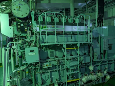
How to check the Tappet clearance in marine diesel engine and it importance

Taking tappet clearance (also known as valve clearance) in a marine diesel engine is a critical routine maintenance task that ensures proper operation of the engine's valve mechanism. Here’s a detailed guide suitable for engine room practice and oral exam preparation. 

What is Tappet Clearance?

Tappet clearance is the gap between the rocker arm and the valve stem (or cam follower and camshaft) when the valve is fully closed. 

It compensates for the thermal expansion of engine parts and ensures valves close completely.

Tools Required

  • Feeler gauge set 
  • Spanner set
  • Torque wrench (for locking nuts)
  • Screwdriver (if adjusting screw type)
  • Manufacturer's manual (for correct clearance values)

When to Take Tappet Clearance

  • After a major overhaul or DECARB
  • At routine intervals (every 2,000–3,000 hours or as per PMS)
  • When abnormal sound or loss of compression is observed

 Step-by-Step Procedure

Always on a cold engine unless specified otherwise
 1. Prepare the Engine
  • Ensure the engine is shut down and properly cooled.
  • Open indicator cocks for safety.
  • Turn off starting air system and tag out the engine.
 2. Find Top Dead Centre (TDC)
  • Rotate the engine manually using turning gear.
  • Set the piston of the unit you're checking to TDC on compression stroke.
Confirm by:
  • Valve overlap of the adjacent unit
  • Exhaust and inlet valves both closed
  • Confirm by firing order and indication on the flywheel
3. Check Clearance
  • Insert the correct feeler gauge between
  • Rocker arm and valve stem (for 4-stroke engines)
4. Move the gauge:
  • Should slide in with slight drag.
  • Too tight = Low clearance
  • Too loose = High clearance
5. Adjust if Needed ( Depends on engine -Refer Maker instructions)
  • Loosen lock nut on the adjustment screw.
  • Turn screw clockwise (decrease) or counterclockwise (increase) clearance.
  • Re-check with feeler gauge.
  • Tighten lock nut and re-confirm.
7. Repeat for All Units

Advantages of Good Tappet Clearance

1.  Ensures Complete Valve Closure
  • Prevents compression loss and blow-by.
  • Avoids hot gases leaking past valves, which can cause burned valve seats.
2.  Maintains Correct Valve Timing
  • Ensures valves open and close at the precise moment in the cycle.
  • Supports proper air intake and exhaust, leading to efficient combustion.
3. Compensates for Thermal Expansion
  • Engine components expand as they heat up.
  • Correct clearance accounts for this, preventing valve sticking or misalignment.
4. Improves Cold Start Performance
  • Proper clearance allows valves to seat fully even in cold conditions.
  • Better sealing means higher compression and easier ignition.
5. Reduces Wear and Tear
  • Prevents hammering action between rocker arm and valve stem
  • Minimizes mechanical noise and stress on camshaft, pushrods, and rockers.
6. Improves Fuel Efficiency
  • Correct valve operation = optimal air-fuel mixture.
  • Leads to complete combustion → less unburned fuel → better SFOC (specific fuel oil consumption).
7. Prevents Valve Overheating
  • A valve that doesn’t close fully can't transfer heat to the seat → leads to burnt valves.
  • Proper clearance ensures valves seal properly and cool during the compression stroke.
8. Supports Engine Power Output
  • Balanced compression and timing mean the engine delivers rated power without misfiring or hesitation.
Pro tips
  • Follow the firing order to check each unit at its TDC compression.
  • Common Clearance Values (Always Check Manual)
  • Always on a cold engine unless specified otherwise
  • Feel for “slight drag” — not loose or tight. This will definitely take some time and experience, so be patient and recheck your work.
  • Use New Feeler gauges — old ones wear thinner with time.
  • Always follow the manufacturer's instructions. If you are working on a new engine, read through the manual before the job.
  • Try out the engine after the adjustment and listen for any abnormal noises
Axial play in Diesel Engine

Axial play in a big end bearing refers to the amount of movement of the connecting rod along the crankshaft axis. It's also known as end play or axial clearance. 
Excessive axial play can cause vibrations, misalignment, and potential failure, while insufficient play can lead to binding and premature wear.

What is Axial Play?

In bearings, axial play is the movement of the inner ring relative to the outer ring along the bearing axis. In the context of a big-end bearing, it's the movement of the connecting rod cap along the crankshaft axis.

Why is it important?

Axial play is a crucial factor in the performance and longevity of bearings.

Consequences of excessive play:
Vibration and Noise: Excessive axial play can cause vibrations and noise due to the connecting rod moving excessively within the big end bearing.

Misalignment: The connecting rod may not be properly aligned with the crankshaft, leading to increased stress and wear.

Potential Failure: In severe cases, excessive axial play can lead to bearing or connecting rod failure.

Consequences of insufficient play:

Binding and Friction: If there's not enough axial play, the connecting rod can bind with the crankshaft, causing excessive friction and heat.

Premature Wear: Insufficient play can lead to premature wear of both the big end bearing and the crankshaft.

Measuring Axial Play:
The axial play in a big end bearing can be measured using a dial indicator.

Proper Installation: Ensure the big end bearing is correctly installed and torqued to the manufacturer specifications.

Normal Range:
The acceptable range of axial play for big-end bearings varies depending on the engine and application.


Chain Coupling


What is a Chain Coupler

A chain coupler is a mechanical device used to connect two rotating shafts in various industrial applications. 

Chain couplers are engineered to transmit torque or tension, absorb misalignment, and provide a secure connection between elements. They are widely used in marine engineering, mechanical power transmission, and railway systems.

Constructed of two-strand chains and two sprockets. Can be connected and separated without moving the equipment by winding the chains over and removing them from the sprockets.


  • Excellent Durability :
The coupling provides outstanding durability with the torque distributed to the strong roller chains and surface-hardened sprocket teeth.
  • Absorption of Large Misalignment :
The clearance between the components absorbs a large misalignment of both shafts.

Limitations:

  • Not suitable for high-speed or high-precision systems.
  • Requires regular lubrication and inspection.
chain coupler with grease

Steam hammering Vs Water Hammering

What is Steam hammering?

It happens when there is direct contact of steam with liquid, as hot steam comes in contact with cooler condensate or liquid, creating a low-pressure zone. The liquid then rushes in to fill the low-pressure zone creating a pressure spike. As the steam flow increases, steam carries the water with it a lot of momentum is created and hammers the line loops with tremendous forces causing a lot of stress.


Effects of steam hammering

  • Cause valve failure.
  • Break pipe welds and rupture piping.
  • Failure in heat exchange or tubes.
  • Crack steam trap and pressure gauges.

How to prevent Steam hammering- Pro tips

  • Have a checklist for the start and shutdown of various steam systems onboard.
  • Correct usage of the warm-up valve.
  • Drain the steam line and make it free of condensate
  • Check and repair insulation to reduce  heat wastage and accumulation of condensate
  • Gradual opening and closing of the valve.
  • Ensure steam traps are working satisfactorily.


What is water hammering?

Water hammering is the sudden pressure surge caused by rapid change in the velocity in the pipeline, which sounds like being pounded with a hammer

It is caused when a fluid in motion is forced to change direction or stop abruptly. When a pump is suddenly stopped, or when an open valve is closed suddenly.

How to prevent Water hammering- Pro tips

  • Reduce operating pressure.
  • Open and close the valve slowly.
  • Installing a pressure reducer.
  • Good pipeline control (start-up and shut-down procedure).


Difference between purifiers and clarifier

What are centrifuges?

A centrifuge is a device that uses centrifugal force to separate component parts of a fluid. This is achieved by rotating the fluid at high speed within a container, thereby separating fluids of different densities (e.g. cream from milk) or liquids from solids.
  • It works by causing denser substances and particles to move outward in the radial direction.
  • At the same time, objects that are less dense are displaced and move to the center.
  • In ships, we use two types of centrifuges ie. purifier and clarifiers 

Definition

  • Purifier is a type of centrifugal separator that we can use to separate two liquids with different densities 
  • Clarifier is a type of centrifugal separator that we can use to separate solid impurities from fuel.

The main difference between the two

Purifier

  1. In a purifier there exists an inference or a line separation between the oil and water, this is achieved using a dam ring. the position and the diameter of the dam ring plays a major role in the creation and maintenance of interface line
  2. Purifier needs to be filled completely with sealing water for the generation of a seal that prevents the oil to leave from the water outlet
  3.  The conical disc has feed holes/distribution holes to help with the interface
  4. It has two outlets clean oil outlet and water outlet
  5. Generally used for lubricating oil
If the interface is broken or misplaced water can go into the clean oil outlet or oil can enter the water outlet, hence disturbing the purification process 

Clarifier

  1. In a clarifier, there is no interface between oil and water, this is achieved by using a sealing ring, which seals the water outlet. this allows the water and impurities to stay within the bowl and is discharged when the bowl disludges
  2. The clarifier doesn’t need to be filled up with sealing water.
  3. The conical discs in a clarifier usually don’t have feed holes in them but if they do, then a disc without any holes is fitted at the bottom of the stack.
  4. It has only one outlet clean oil outlet
  5. Generally used for fuel oil depending on fuel density and design

Letter of protest

At times dispute or deviation may occur when taking bunkers, loading/discharging cargo. The most common protest from an engineer's perspective is related to bunkers although one can be written for almost any other matter.
  • It is a recorded written communication expressing dissatisfaction on the part of the one-party concerning any disputes, holding the other party responsible strictly speaking LOP is not a legal document but a paper containing the account of facts.
  • This may help substantiate a claim and may prove to be useful if properly filled when trying to resolve the dispute later on. 
  • Bear in mind to keep it as brief and as clear as possible and not to express any option whatsoever.
  • Be sure to make all appropriate entries in the ship's logbook.

Various disputes leading to LOP-(bunkering)

  • Difference in ships/barge figures for the quantity supplied
  • Delay in supply bunker 
  • Slow pumping rates
  • Refuse in witnessing samples taken onboard
  • supply off-spec bunkers
  • Delay for connecting hoses
  • No authentic calibration table for bunkers
  • Water in barge/shore tank before commencing
  • Fouled mooring ropes
  • Not complying with Singapore bunkering procedure

Example of LOP

Port:xyz, Voyage No.:ABC
Supplier: XYZ ,Date: xx/xx/xxxx
To: Xyz

From:xyz
Ship:Xyz,

Re: Difference in quantity supplied/received
Dear Sir,

On behalf of my Owners, I hereby note protest due to the difference in the supplied/received bunker figure.

Bunkers supplied: MT
Ship’ figure: MT
Difference: MT 

I, therefore, reserve the rights of my Owners and Charterers to refer to this matter at some later date and take any actions, or make any claims, as they may deem necessary.

Yours faithfully,
XYZ

Bumping clearance on main air compressor

  • Bumping clearance is the clearance between the top of the piston and the cylinder head when the piston is in T.D.C.
  • This is clearance should be checked on ever overhaul and should be within limits specified in the manual

Too less a clearance
  • Posses a risk of the piston hitting the cylinder which may lead to dangerous mechanical failure.
  • Turn the compressor manually prior running to ensure no mechanical resistance to the piston 
Too large a clearance
  • less air is drawn in the suction side as it retards the formation of vacuum due to large clearance
  • drop the volumetric efficiency 
  • longer run time
Measurement of clearance
  1. Place a lead ball or a lead wire on top of the piston
  2. Turn the compressor by hand
  3. Measure the thickness of lead wire using a vernier caliper
  4. Compare with manufacturer manual
  5. Adjust if required
Reason for change in clearance
  • Increase in clearance can be due to wear in bottom end bearing
  • Using wrong gaskets on the head can reduce the clearance

Precaution
  • Use only original and genuine spare parts from the manufacturer
  • Check size of the gasket used in every overhaul

    CENTRIFUGAL PUMP TROUBLE

     Suction troubles

     1. Pump not primed
    2. Pump or suction pipe not completely filled with liquid
    3. Suction pipe lift too high
    4. Insufficient margin between suction pressure and vapor pressure
    5. Excessive amount of air or gas in liquid
    6. Air pocket in suction line
    7. Air leaks in suction line
    8. Air leaks into pump through stuffing box
    9. Foot valve too small or partially clogged
    10. Inlet of suction pipe insufficiently submerged
    11. Water seal pipe plugged
    12. Seal cage improperly located in stuffing box, preventing sealing fluid entering space to form seal

    System troubles

    13. Speed too low
    14. Speed too high
    15. Wrong direction of rotation
    16. Total head of system higher than design head of pump
    17. Total head of system lower than design head of pump
    18. Specific gravity of liquid different from design
    19. Viscosity of liquid different from design criteria
    20. Operation at very low capacity
     21. Parallel operation of pumps unsuitable for such operation

    Mechanical troubles 

    22. Foreign matter in impeller
    23. Misalignment
    24. Foundations not rigid
    25. Shaft bent
    26. Rotating part rubbing on stationary part
    27. Bearings worn
    28. Wearing rings worn
    29. Impeller damaged
    30. Casing gasket defective permitting internal leakage
    31. Shaft or shaft sleeves worn or scored at the packing
    32. Packing improperly installed
    33. Incorrect type of packing for operating conditions
    34. Shaft running off center because of worn bearings or misalignment
    35. Rotor out of balance resulting in vibration
    36. Gland too tight resulting in no flow of liquid to lubricate packing
    37. Failure to provide cooling liquid to water cooled stuffing box
    38. Excessive clearance at bottom of stuffing box between the shaft and casing, causing packing to be forced into pump interior
    39. Dirt or grit in sealing liquid, leading to scoring of shaft or shaft sleeves
    40. Excessive thrust caused by a mechanical failure inside the pump or by the failure of the hydraulic balancing device, if any
    41. Excessive grease or oil in bearing housing or lack of cooling, causing excessive bearing temperature
    42. Lack of lubrication
    43. Improper installation of antifriction bearings (damage during assembly, incorrect assembly of stacked bearings, use of unmatched bearings as a pair, etc.)
    44. Dirt getting into bearings
    45. Rusting of bearings due to water getting into housing
    46. Excessive cooling of water-cooled bearing resulting in condensation in the bearing housing from moisture in the atmosphere

    COLD WEATHER PRECAUTION

    Crew Protection  

    1. Several layers of clothing (instead of one heavy suit) is preferable as air trapped between the layers of the clothing provides greater insulation and consequently less loss of body heat.
    2. Use of clothing with some ventilation decreases perspiration which can freeze. Wet flesh freezes faster than dry flesh.
    3. Whilst working it is natural to perspire, but do not remove clothing whilst in an exposed environment, come into the accommodation to dry off.
    4.  As far as possible work with back towards the wind.
    5. Gloves to be sufficiently loose for circulation to be maintained.
    6. Hoods/caps to be worn with ears covered. Much body heat is lost through unprotected head and neck.
    7.  Never rub a numb area as this could damage the frozen flesh.
    8. In extreme temperatures, feel your cheeks and nose with your fingers.  No sensation means the likelihood of frostbite is present, so enter a warm area as soon as possible.
    9. Frost-bite and hypothermia are very real dangers associated with cold weather. Guard yourself carefully against them.
    Vessel Precautions 
    •   Fire Lines: Drain the fire-main lines and leave the drains open. Leave a hydrant on the lowermost exposed deck open. Drain the straight-drops of the fire-line around the Accommodation.  Drain the anchor-wash lines.Tag the fire pumps starting panel so that deck-water is not started inadvertently.
    •   Shut the fresh water line to the main deck and drain the line. Shut the external fresh water lines to all individual accommodation external decks and drain the lines.
    •  Drain the bridge window wash water line and leave the drain open, never attempt to start the system in sub-freezing temperatures.
    •   Ensure only seawater ballast is retained onboard – exchange ballast if necessary
    • Continuously circulate the ballast.
    • Start motors/pumps of gangways/hoists/ provision cranes/hatch covers / cargo-handling gear well in advance of their use. 
    •  All exposed movable parts (butterfly nuts-bolts, flap hinges, vents, valve spindles, sounding pipe/temperature pipe caps, hydrant wheel spindles, steel door dogs, etc.,) to be kept liberally covered with grease.  A little anti-freeze mixed into the grease is very effective.
    • Ensure space-heaters where fitted to be kept ON.  (forward stores / under-deck spaces / Emergency Fire pump room / steering flat / Emergency Gen room / all hydraulic pump rooms).
    • All exposed electric/air motors (gangways, lifeboats, crane, davits etc.,) to be securely covered. Drain the air pipeline filters of water.
    • Slacked down fuel tanks / FW tanks / Jerry cans in the lifeboats.  Ensure lifeboats are fully covered and secured properly.  Lifelines, if not fully covered, to be coiled inside the boats with the standing parts lead through the forward / aft openings in the covers.
    • Lifeboat: Ensure that lifeboat engine heaters are ON and keep pilot-start cans in boats ready for use.
    •  Use only 100% glycol / antifreeze for engine coolant. Do not add water, as it will freeze around -20 deg C. Take a sample of coolant from the Emergency generator & lifeboats and keep in Meat room, to check the effectiveness in sub-zero temperatures. 
    • Incinerator: To run ½ hour on DO before stopping. Keep Waste Oil tank temperatures around 100 deg C all times. Never shut steam fully.
    •  Diesel Generator: Run ½ hour on DO before stopping. After stop, free-up fuel racks with Kerosene + LO. Check racks are free before starting the DG each time. Shut Sea water valves for the stopped DG. Run the stopped DG at least ½ hour each day. Turbocharger washing for each DG should be carried out before entering the cold / sub-zero area.
    •  Seawater temperature control valve be set at 30 0C for recirculation (though it will not help much when ME is stopped).
    •  Engine room ventilation blowers: Keep only one blower ON (Above FD fan). Keep flaps shut above DG and purifier room, to avoid cooling due to ambient air. ER funnel flaps SHUT. Door between ER and Steering flat to be kept OPEN (close this if PSC inspection). Steering exhaust fan to be stopped, vent shut. Natural air inlet be shut to avoid cooling by ambient air.
    •  FO transfer pump: Keep steam tracing ON. Suction filter does not have the steam tracing line, so keep the steam hose ready in case to use it. FO transfer to be done manually (do not put on Auto) under supervision. Check pump amps while transfer. Steam heating to ALL bunker tanks to be ON always. Clean transfer pump filter before entering the cold / sub-zero area.
    •  FO overflow tank: Keep the steam heating ON. Bring levels low, by transferring to Waste oil tanks before entering cold/sub-zero areas
    •  BSOT tank: Keep the steam heating ON. Bring levels low, by transferring to Waste oil tanks before entering cold/sub-zero areas. If thick cold sludge is transferred by sludge pump, it may choke and damage the pump. So better avoid it.
    • Bunker System: Blow through the FO & LSMGO lines on deck from a manifold to each individual tanks. Ensure the pipeline is clear before entering the cold/sub-zero areas. Line up the tanks which have to bunker and keep the valves in OPEN condition (depending on your judgment). Clean the air vent mesh. Apply grease + glycol on the sounding pipes of FO tanks on deck. Before bunkering ensures the air vents for each tank is clear.
    •  Hot Well: Boiler cascade tank temperatures to be around 80 0C. Bypass the atmospheric cooler if required.
    •  At least one portable steam hose to be kept ready of sufficient length (approx. 5 m) for use in an emergency.
    •  ME under-piston drain line: After ME stop, blow the line with Steam till scavenge drain tank. Also, blow steam and clear passage from the line to each unit.


    LUBE OIL SAMPLING

    lube oil sample
    Lube oil sample
    Regular lube oil sample is taken onboard either to test oil using the onboard test kit or to be landed for shore analysis.

    Carry out risk assessments a precaution wear proper PPE like hand gloves and face shield as the oil can be hot when taken from running machinery.

    • The first step is to locate an approved sampling point for the system. Typically air vent of filters, drain of gauge glass, etc.
    • Drain around 1 to 2 liters of oil so as to remove impurities from the sampling point.
    • Use clean sample bottles to ensure the best result.

    Always sample the system from the same sampling point.
    Ensure the system is under stable and steady conditions before sampling.

    scavenge space cleaning and inspection

    2-stroke main engine
    main engine
    First of all scavenge space needs to be treated like an enclosed space so it goes without saying all checks, permits need to be done prior entry.So in this article would like to lightly thread upon a few pointers.

    Checks prior to the job

    1) It is very important to discuss the job in the management meeting among top four. Good understanding between the department head helps solve half the hassle.Weather, duration of the job, navigational hazard, etc or any other limitation should be discussed and made clear to all party

    2) Proper toolbox meeting needs to be held and everyone needs to be briefed on the job, safety, and responsibility.

    3) Make sure the engine is sufficiently cool before opening up the scavenge doors and under piston dooor.
    •  nuts, bolt, and gasket for the door need to keep safely and accounted for
    • make sure no foreign material get into the space 
    4) main engine needs to be properly locked out
    • Contol to main engine is kept to ECR and telegraph placed a stop
    • Auxillary blower need to be in manual
    • Starting air valve to the main engine needs to be shut 
    4) Scavenge space need to be properly ventilated
    Cleaning material, portable lights, portable firefighting equipment, SCABA for enclosed space rescue need to be kept standby.

    5) Prior to entry,scavenge space atmosphere need to be tested and enclosed space permit complied to 
    •  O2 level-20.9%
    • HC level-0% LEL
    • and other toxic gases- 0%

    Checks after the job

    1) Before closing the scavenge door make sure
    • That there are no personnel left inside the space, all engineers and crew need to be accounted for.
    • Tools, rags etc are left behind , a responsible person needs to inspect the place for the same 
    Surprising  there have been accounts of such accidents so be absolutely sure before closing the door 

    2) Account for all the nuts and bolts 
    3) Use proper gaskets to seal the door and use correct tightening  procedure

    Things that may go wrong 

    1) Never perform the job when the vessel is experiencing bad weather unpredictable engine movement due to outside force can be fatal
     2) Since scavenge space is an enclosed space there is high risk for trips and accident so a formal risk assessment need to be taken and a proper plan for enclosed space rescue need to be drawn prior job
    3) At times due to some navigational hazards, OOW might ask for engine
    • Calm down and call off the job ASAP
    • Make sure all personnel are out of the space and  scavenge space if free of tools and rags
    • Fix back all the doors since time is a factor tightening 4 bolts in the opposite direction per door  is sufficient, the door will hold. 
    • Give control to bridge after confirming all door secured
    4) If the door is not tightened properly or using a damaged gasket that will lead to an annoying leak  
    5) If a rag is left behind it can chock the scavenge drain that might lead to a scavenge fire


    Partial discharge in purifier


    • Partial discharge occurs in Mitsubishi hidden series(GSH-1 specification model only)
    • When the purifier detects a loss in back pressure on the line connecting the water outlet to the purifier inlet control unit sends a signal for partial discharge

    Partial discharge


    • In case of partial discharge (GSH-1 specification model) ,the operating water for partial discharge is regulated by the solenoid valve SV9 and introduced into the bowl closing water pressure chamber via feeding device. 
    • When the bowl closing water pressure chamber has been filled up; the bowl opening water overflows into the bowl opening water pressure chamber; depressing the main cylinder to open the bowl instantly, causing the purifier to partially discharge


    Storm Valves

    Storm valves are mainly found on ships sanitary systems having a ship side exit.
    A Storm valve has two functions, isolation and non-return.  Generally consisting of a hand operated or actuated on/off valve and a swing check valve. 
     Storm valves allow outflow over the ships side while preventing sea water entering the system during heavy seas.
    • A check valve placed at the end of soil or scupper pipes discharging through the ship side near the waterline.
    • It allows the water to discharge overboard but prevents seawater from backing up the pipe.storm valve in ship

    why are some of the overboard valve (bilge v/v, boiler blow down) v/v place in reverse order

    No i am not drunk and it is not a design flaw.................................

    In some of the ships the non-return overboard valve especially for the OWS bilge overboard v/v and the boiler blow down v/v might be placed in reverse ie. the direction of valve will be from outward to inward direction.

    The main reason for such a odd arrangement is as the ows overboard v/v and boiler blow down valve are frequently used (opened and closed frequently depending on ships operation). 
    As the direction of the valve is reversed it prevents sea water entering the engine room when a basic maintenance such as gland replacement is done provided the valve is shut and it holds.

    SQUAT EFFECT

    • The squat effect is the hydrodynamic phenomenon by which a vessel moving quickly through shallow water creates an area of lowered pressure that causes the ship to be closer to the seabed than would otherwise be expected.
    •  This phenomenon is caused when water that should normally flow under the hull encounters resistance due to the close proximity of the hull to the seabed.Leonardo's law causes the water to move faster in water level (where the section is smaller); according to Bernoullì's theorem, a velocity increasing determinates a low-pressure area so that ship is pulled down. This squat effect results from a combination of vertical sinkage and a change of trim that may cause the vessel to dip towards the stern or towards the bow.
    • The squat effect is approximately proportional to the square of the speed of the ship. Thus, by reducing speed by half, the squat effect is reduced by a factor of four.
    • The squat effect is usually felt more when the depth/draft ratio is less than four or when sailing close to a bank. It can lead to unexpected groundings and handling difficulties.

    Fundamental difference between PIPES and TUBES

    There is always a doubt among several marine engineers about the basic difference between pipes and tubes especially when it comes to spares order.

    Pipes

    • Pipes are classified by schedule and nominal diameter. For example, a 250mm nominal diameter and schedule 80 pipes.
    • In pipes, all the fittings can be matched by nominal size and schedule.
    • For example, a schedule 40 one inch pipe will have fittings specified by the same name. These pipe fittings would not fit a 1” tube.
    • Pipes are always round or cylindrical.

    Tubes

    • Tubes are classified by outside diameter and thickness. For example 10mm copper tube 2 mm thickness.
    •  Tubes may be square, rectangular and cylindrical.
    Nominal Diameter
    • The nominal diameter is not internal diameter but similar to it.
    • The nominal diameter is the approximate inner diameter of the pipe it is a rounded figure easier to use and remember
    •  By prescribing the nominal size of the pipe all the different fittings can be selected based on the same nominal diameter, without physically checking the dimensions and compatibility of each component.
    Schedule of Pipes
    • In ships, we generally use schedule 40 for light-duty and schedule 80 for heavy-duty. 
    • There are however many other schedules that have been incorporated due to improvement in metallurgy and increased pressure demands.
    • As a general thumb rule, as the schedule increases the wall thickness increases and the ID deceases.

    Cappuccino effect

    The Cappuccino Effect, the frothing/bubbling effect caused by compressed air blown through the delivery hose. 
    • The aerated bunkers, when sounded, will give the impression that the fuel is delivered as ordered, when in fact when the entrapped air in suspension settles out of the fuel oil the oil level drops, and a shortfall is discovered.

     In large bunker deliveries, this could be considerable with a huge financial loss.

    Sign to look out for

    • Look out for any signs of foam on the surface of the fuel or excessive bubbles on the sounding tape.
    • Bunker hose jerking or whipping around
    • Gurgling sound when standing in the vicinity of bunker manifold.
    • Fluctuations of pressure indication on the manifold pressure gauge. Unusual noises from the bunker barge
    • Bunker hose jerking or whipping around.
    • Gurgling sound when standing in the vicinity of bunker manifold.
    • Fluctuations of pressure indication on the manifold pressure gauge.
    • Unusual noises from the bunker barge
    • Remember whenever in doubt or have concerns always issue a letter of protest

    MEO CLASS 4 function 6b (oral question)

    • Ref charging methods ,where is the point for charging ?
    • where else u can have the point to charge the ref....explain the method???
    • Ows how it works ? what principle ? why do u fill it with sea water ??
    • Why a Purifier vibrate? What is there to control it ??
    • Reason for purifier overflow
    • Cyl head dcarb...what are the things u wil check? How wil u clean all passages?
    • Comp running too much time what can be the reasons ?
    • How will u start FWG...tel him that u start the sea water pump and tel him that u should wait till there is a good vacuum generated.... then only give jacket water feed slowly... dont create thermal stress...
    • How to start purifier...??
    • Draw the 4 ram steering gear and explain how it works ? how are the pumps controlled ?
    • What is 100% redundancy ?
    • Draw Viscothem and explain ? principle ?how it works ? what it controls ? is it fuel supply ???? It controls steam control valve to the heater
    • Draw Boiler feed water line ...in which line is the feed water regulater ? is it in the main line or aux..
    • Reason for 2nd stage compressor valve to lift
    • bunker check list and procedure before bumkering
    • All clearances in turbocharger
    • All checks done in exhaust valve for both 2s and 4s engine (spindle ,valve seat............)

    MEO CLASS 4 IMPORTATION QUESTION FOR FUNCTION 3 ORALS

    1.  what is mean by racking
    2.  duct keel?
    3.  sheer strake?
    4.  free board?
    5.  minimum summer draught?
    6.  E/R bilge transfer regulation?
    7.   CO2 fixed fire fighting system regular checks? why fire pump have priming arrangment?
    8.  what check done in fire pump?
    9.  all annexes name 
    10.  stcw chapters 
    11.  annex 2 applicale to which ship n y?
    12.  annex 3 applicable to which ship n y?
    13. MLC and rest hour regulation
    14. ISPS regulation
    15. new regulation for SCABA
    16. why do we use nitrogen in fixed DCP extingusher in gas ships
    17. Reason or having a spring loaded  non return drain valve for steering gear room

    Followers